Wear scar is the metric used to determine the quality of oils, greases and fuel lubricity. Visual observation is widely accepted method to detect and quantify the wear on the tribologically tested specimens. However, the difficulty in the visual observation that is also subjective in nature can increase the error and test variability (see Fig. 2). However, this problem can be overcome using advance artificial intelligence algorithms such as ai.ducom.com (powered by MOOHA).
This software platform is free to use (see Fig. 1) and it can automate the complex process of identifying the wear scar from tribometers like four ball testers, HFRR, ball on disc, Reichert tester and others.
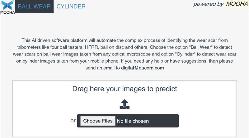 Figure 1. Browser-based software for automated edge detection.
How does the wear edge detection vary from person to person?
Two operators have measured the same ball wear scar using the same microscope. According to the visual observation done by the first operator (see Fig. 2 - green), the ball MWSD of tests 1, 2, 3, 7 and 9 were out of acceptance range (HFRR, ASTM D6079, ref fluid A), whereas the measurements made by the operator 2 (see Fig. 2 - blue) were within the acceptance range. Who is correct?
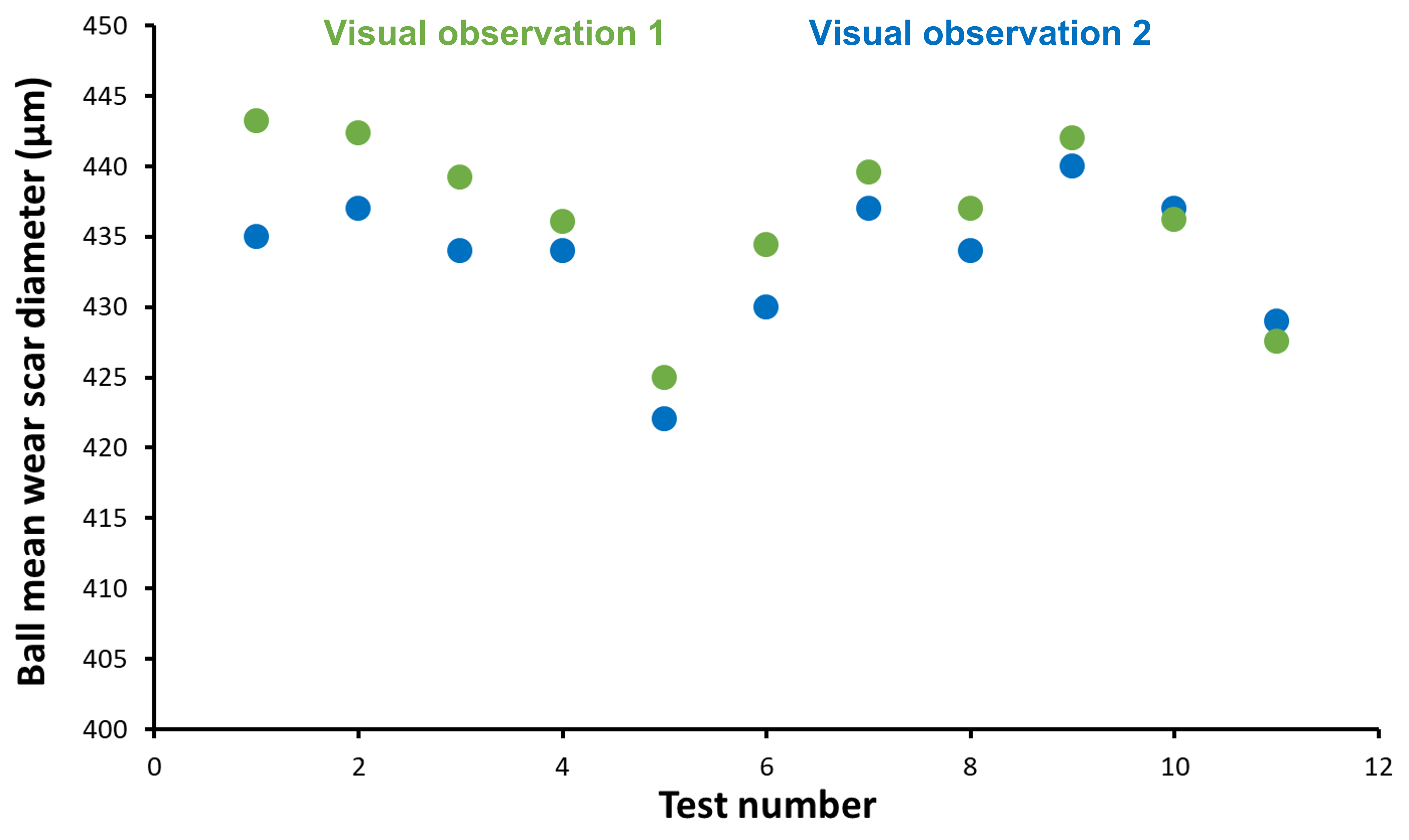
Figure 2. Ball mean wear scar diameter measurements done by two different operators.
Principle of Operation
MOOHA with an AI algorithm was developed to identify the wear scar edges and automatically quantify the wear. As shown in Figure 3, after pre-processing of a dataset, a neural network extracts the features of the uploaded image (i.e., original) and reconstructs it to a binary image (i.e. prediction). During pre-processing, the image is cleaned and X-Y axis are drawn around it.
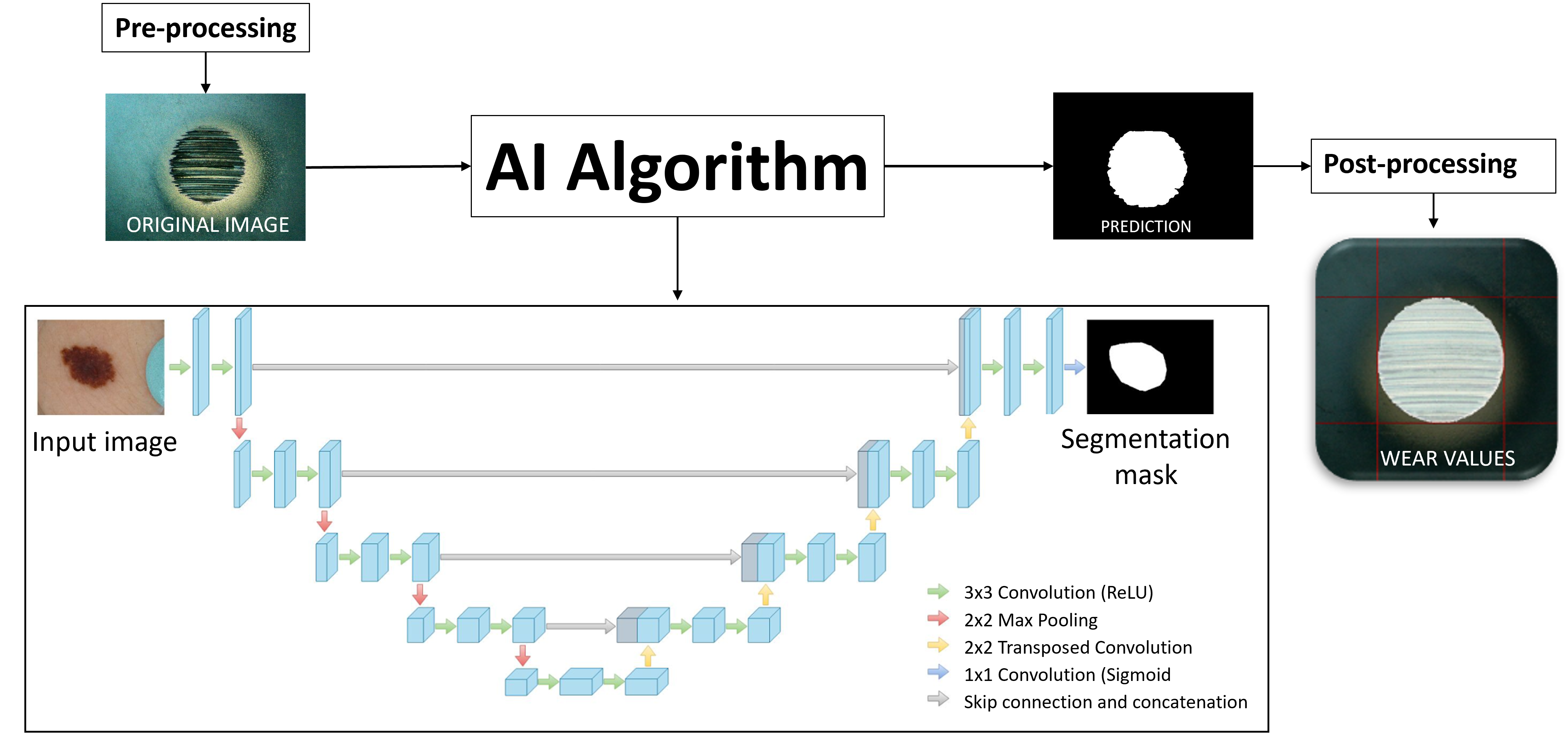 Figure 3. AI algorithm developed for automated wear scar prediction.
How does it work? Click on ai.ducom.com. On the top left (see Fig. 1), select "ball/disk wear" if you want to predict the wear on specimens tested using a four ball tester, HFRR, ball/pin on disk or similar instruments. Select "cylinder wear" if you want to predict the wear on specimens tested using Reichert tester.
- Click on "choose file" or drag the images you want to predict.
- Insert the ratio "pixel/micrometers" (you can find this information in the settings for your microscope or image acquisition system). Click "set for all" in case of multiple images.
- Move the guidelines to center the wear scar at the center and click "crop".
- If necessary, rotate the image (for a correct prediction, the wear scar must be straight).
- Click on the blue thick mark once you are ready. In a few seconds, the AI algorithm will automatically predict the wear length, wear height, mean wear scar diameter and area.
 Figure 4. Prediction of ball wear scar using ai.ducom.com
The AI algorithm gives you the possibility to insert your own measurement and it automatically calculates the error (in %) between the prediction and the visual observation (i.e., Predicted vs. Microscope Error (%)).
 Figure 5. Prediction of ball mean wear scar diameter and output measurements.
Here below we report a few complex cases of ball, disk and cylinder wear scars that were detected precisely by our AI algorithm. Please note that the images taken by the microscopes and camera/mobile phones are processed by this algorithm.
A. Images from Optical Microscopes
Wear scar type: Ball , Test lubricant: Low Sulphur diesel fuel, Test instrument: Ducom High Frequency Reciprocating Rig (HFRR 4.2), Image acquisition method: Optical microscope
Difficulty Level: The edges of the wear scar are not well defined (red); the wear scar is small; oxidation might trick the definition of wear edges (blue).
Wear scar type: Ball, Test lubricant: Low viscosity engine oil, Test instrument: Ducom High Frequency Reciprocating Rig (HFRR 4.2), Image acquisition method: Optical microscope
Difficulty: The edges of the wear scar are not well defined (red); the wear scar is small; there are a few scratches that looks going outside the wear scar edges (yellow).
 Wear scar type: Ball, Test lubricant: Low viscosity oil, Test instrument: Ducom High Frequency Reciprocating Rig (HFRR 4.2), Image acquisition method: Optical microscope
Difficulty: The edges of the wear scar are not well defined (red); the wear scar is small; oxidation (blue), material transfer (green) and delamination (orange) might trick the definition of wear edges.
 Wear scar type: Disk, Test lubricant: Reference fluid B (DFB20), Test instrument: Ducom High Frequency Reciprocating Rig (HFRR 4.2), Image acquisition method: Optical microscope
Difficulty: The wear scar is uneven and makes it difficult to calculate the area; delamination at the edges might affect the wear scar area measurement (orange).
Wear scar type: Cylinder, Test lubricant: Metal Working Fluid, Test Instrument: Ducom Reichert Tester, Image Acquisition Method: Optical Microscope.
B. Images from Digital Image Acquisition System (IAS)
As shown in Figure 6, the IAS is used for in situ imaging of test balls in the ball pot from the four ball tester.
 Figure 6. Image Acquisition System with ball pot.
Wear scar type: Ball, Test lubricant: Motor oil, Test instrument: Ducom Four Ball Tester (FBT-3), Image acquisition method: Image Acquisition System – IAS (CCD camera)
Difficulty: The wear scar is uneven; marks on the ball (outside the wear scar) might affect the wear scar measurement (purple).
 Wear scar type: Ball, Test lubricant: Transmission oil, Test instrument: Ducom Four Ball Tester (FBT-3), Image acquisition method: Image Acquisition System – IAS (CCD camera)
Difficulty: Marks on the ball (outside the wear scar) might affect the wear scar measurement (purple); delamination might trick the edge definition (orange).
Wear scar type: Ball, Test lubricant: Grease, Test instrument: Ducom Four Ball Tester (FBT-3), Image acquisition method: Image Acquisition System – IAS (CCD camera)
Difficulty: The wear scar is uneven and very difficult to understand where does the wear end; delamination might trick the edge definition (orange).
 Wear scar type: Ball, Test lubricant: Grease, Test instrument: Ducom Four Ball Tester (FBT-3), Image acquisition method: Image Acquisition System – IAS (CCD camera)
Difficulty: The wear scar is uneven and very difficult to understand where does the wear end; material transfer (green), deep grooves (grey) might trick the definition of wear edges.
 Wear scar type: Ball, Test lubricant: Bio-lubricant, Test instrument: Ducom Four Ball Tester (FBT-3), Image acquisition method: Image Acquisition System – IAS (CCD camera)
Difficulty: Uneven wear scar and edges not well defined; oxidation (blue), delamination (orange) might trick the definition of wear edges.
C. Images Taken by Mobile Phone
Use the camera on your phone to take a picture of the worn cylinder and upload the same image on ai.ducom.com. The algorithm will instantaneously detect the wear scar region and quantify wear. For accurate measurement of the wear scar please follow these instructions below.
- Select "line" or "point" to trace the edges of the cylinder holder (see Fig. 7). Press confirm to proceed with the prediction.
- Move the guidelines to center the wear scar at the center and click "crop".
 Figure 7. Wear prediction of a cylinder using an image takeb by mobile phone.
- If necessary, rotate the image (for a correct prediction, the wear scar must be straight).
- Click on the blue thick mark once you are ready. AI algorithm will automatically predict the wear length, wear height, mean wear scar diameter and area.
Wear scar type: Cylinder, Test lubricant: Metal Working Fluid, Test instrument: Ducom Reichert Tester, Image acquisition method: Camera in Samsung Mobile Phone ( S10)
- Detect and measure wear scars from anywhere and anytime (cloud based system)
- Overcome the human error and reduces the test variability (see Fig. 8)
 Figure 8. Ball mean wear scar diameter measurements done by two different operators and ai.ducom.com
%20-%20PNG.png?width=925&height=246&name=Ducom%20-%20Logo%20-%20Full%20-%20Vector%20(90%20Gray%20and%20Light%20Blue-Inverted)%20-%20PNG.png "Ducom - Logo - Full - Vector (90 Gray and Light Blue-Inverted) - PNG")


.png?width=564&height=150&name=Ducom%20-%20Logo%20-%20Full%20-%20Vector%20(90%20Gray%20and%20Light%20Blue-Inverted).png "Ducom - Logo - Full - Vector (90 Gray and Light Blue-Inverted)")


_Cover.jpeg)