Renewable technologies such as concentrated solar mirrors, solar photovoltaics, biomass, hydroelectric turbines, wind turbines, etc. have been shown to be a sustainable solution for the increase in global energy demand. In 2015, renewable energy represented 19.3% of global energy consumption (Source: Renewable Energy Network for 21 Century). As illustrated in Figure 1, the total renewable energy production was 2017 GW in 2016, where the solar photovoltaics (PV) technology contributed a share of 303 GW, which is lower than 487 GW produced by wind power. However, solar power grows at a rate larger than wind power. For instance, solar PV accounted for 47% of new infrastructure for renewable energy in 2016.
Figure 1. Renewable energy production in 2016.
SOLAR POWER
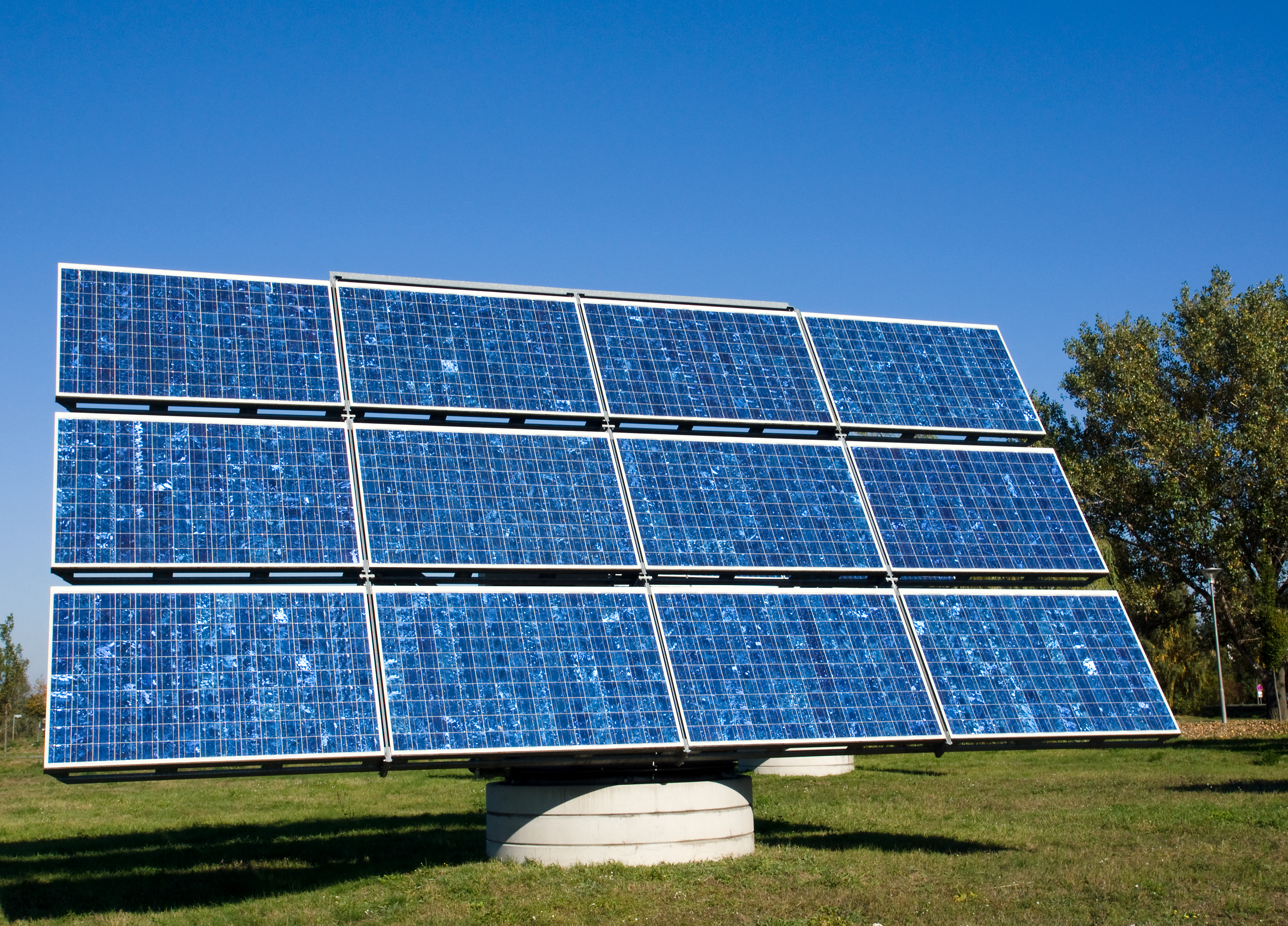
Solar power (PV and solar mirrors) is known for its poor energy efficiency that is less than 20%. Compared to wind turbines, solar power technologies are less efficient but they are considered to have better reliability, pollution free (sound), and ease of maintenance. However, accumulation of dust (soiling) and repetitive impact of sand particles (erosion) affect the performance of solar power technologies (Figure 2).
 Figure 2. Glass panels protecting the solar PV being exposed to dust (soiling) and solid particle erosion.
Glass panels are used to protect solar PV. Light transmits through the glass and reflects from it before reaching the PV cells. To improve light transmission, antireflective coatings are used but they are susceptible to erosion by sand particles carried by heavy winds. Also, accumulation of dust on solar panels (soiling) affects light transmission but soiling is a reversible process.
In concentrated solar power plants, mirrors are used as reflectors to heat water and produce steam to propel turbines for electricity production. Erosion of reflectors caused by sand particles will result in diffusion of light and decreases the specular reflectance that is much needed for steam generation (Figure 3). However, erosion is a nonreversible factor that decreases the energy efficiency in solar power plants.
 Figure 3. Specular reflectance of an undamaged mirror (A) and diffused reflectance due to erosion.
EROSION
Erosion is a process of wear by progressive loss of materials caused by the impact of solid particles. Mechanism of wear can be categorized into the brittle or ductile mode of failure. Brittle failure is caused by fracture whereas ductile failure involves severe plastic deformation. Surface features of a ductile failure include ploughing, shearing, ripples and lip formation. However, there are chipping, surface craters, and cracks observed on surfaces after brittle type failure caused by solid particle impact. Erosion, often expressed as the weight loss per gram of solid particles, is a function of material properties (hardness, flow stress, toughness, elastic modulus) operating parameters (mass, size, shape, particle velocity, impact angle), and environment conditions (humidity and temperature). Investigating the role of these factors in erosion can help understand the mechanism of erosion better.
/AJT%20Videos%20and%20Images/AJT%20at%201000%20C.png?width=475&name=AJT%20at%201000%20C.png) Ducom Solid Particle Erosion Tester
Ducom Solid Particle Erosion Tester
Mirrors, glass and antireflective coatings as reflectors are brittle materials that are exposed to dust (or solid particle impact). In this case, brittle failure dominates the loss of materials. The kinetic energy of the solid particle is converted to plastic deformation, wear, and fracture (Figure 4).
 Figure 4. Erosion in brittle materials. Hertzian contact between a solid particle and substrate at 90° (A), cracks are initiated around the contact due to dislocations (B), growth of cracks (C) and chipping tocrater formation (D).
The critical particle velocity needed to initiate the cracks has been empirically determined in a single particle erosion study by Evans et. al in 1978. As expressed in Equation 1, the critical velocity (V ) is in a relationship with fracture toughness (K ), particle radius (r), hardness (H) and particle density (ρ).
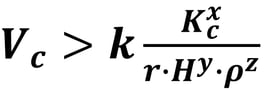
Equation 1
Where, k is a constant and x, y, z are power exponents of toughness, hardness, and density, respectively.
It can be assumed that cracks will not be induced when the particle velocity is lower than the critical velocity.
Equation 2, as given by Wiederhorn et. al. in 1979, can be used to calculate the force (F) exerted by a solid particle carrying a mass (m) after making a contact.
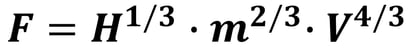 Equation 2
Where, V is the particle velocity.
This force is responsible for crack growth and chipping.
In general, the elasticplastic theory developed by Wiederhorn et. al. can be used to estimate the erosive wear rate (E) for brittle materials, as expressed in Equation 3.
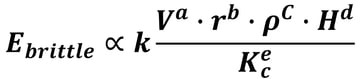 Equation 3
Where, k is a constant and a, b, c, d, and e are power exponents.
In brittle materials, although the erosive wear is caused by fracture, some degree of plastic deformation occurs due to the impact of the particles at a very low angle, for example, at 15°. Here, the erosive wear rate can be estimated using the model developed by Sheldon et. al in 1972, as expressed in Equation 4.
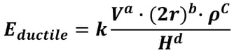 Equation 4
Apart from the lower particle impact angle, the transition from brittle to ductile failure is caused by the particle size. Smaller particles tend to decrease the critical velocity for initiating the cracks, as deduced from Equation 1. This can cause some degree of
ploughing on the surface, a characteristic of ductile failure.
EROSION IN SOLAR PLANTS
In solar power plants, the extent of erosion is measured in loss of specular reflectance for solar reflectors and loss of optical transmission for the glass and its antireflective coatings for solar PV. A study by Bouzid et. al. (J. Eur. Ceram. Soc., 2000, 20: 481488), has demonstrated that erosion of glass can cause a loss in its optical transmission by up to 36%. A recent laboratory scale erosion test by Karim et. al. (Solar Energy, 2015, 118:520532) has shown a relationship between the loss of specular reflectance of mirrors and several erosion parameters such as particle velocity, size, shape and impact angle. A summary of this relationship is shown in Table 1.
Table 1. Relationship between loss of specular reflectance and erosion test parameters as determined using a laboratory scale erosion tester.
Laboratory scale erosion test is critical for rapid screening of erosion resistant materials. Testers used for this purpose should fulfill two basic requirements, as explained below,
1. Reproduce the field conditions in the laboratory, such as temperate, particle size, particle velocity, angle of impact, and flux. Based on Ducom Instruments’ literature survey, these field conditions are tabulated as described in Table 2.
2. Accurate control and measurement of the operating parameters to obtain repeatable and reproducible erosive wear.
Table 2. Description of parameters that influence erosion of solar powered plants based on Ducom Instruments’ literature survey.
SINGLE PARTICLE EROSION
Predicting the life of components in the solar power plants is critical for product development and maintenance. Erosion test with the flux of solid particles that impact the surface is a random process and is difficult to model. However, a single particle erosion test, such as using an indenter in a scratch tester (Figure 5) can be more useful and can complement the results obtained using an erosion tester.
 Figure 5. Random process of solid particles contact with the substrate in an air jet erosion tester (A) and a systematic process of solid particle contact with a substract in a scratch tester (B).
Scratch tester provides a better control and measurement of a single particle dynamics such as sliding velocity, sliding distance, penetration depth, impact force, single or multiple scratches and particle size/shape in contact with a substrate. In addition, it is possible to measure the substrate response to the particle contact in real time by acquiring the friction force and penetration. The acoustic emission sensing feature in the scratch tester can be used to measure any cracks initiated during the scratching.
 Ducom Unitest Scratch
%20-%20PNG.png?width=925&height=246&name=Ducom%20-%20Logo%20-%20Full%20-%20Vector%20(90%20Gray%20and%20Light%20Blue-Inverted)%20-%20PNG.png "Ducom - Logo - Full - Vector (90 Gray and Light Blue-Inverted) - PNG")


.png?width=564&height=150&name=Ducom%20-%20Logo%20-%20Full%20-%20Vector%20(90%20Gray%20and%20Light%20Blue-Inverted).png "Ducom - Logo - Full - Vector (90 Gray and Light Blue-Inverted)")
/AJT%20Videos%20and%20Images/5.Reproducability.jpg)
/AJT%20Videos%20and%20Images/Other%20Images/Microscopy%20images%20of%20three%20different%20catalyst%20used%20as%20erodent%20in%20G76%20tests.png)