Coatings is one of the widely used surface modification method which enhances the tribological performance of a system. Durability and adhesion to substrate are important parameters and scratch test is a widely used technique for quick screening and understanding of the behavior of coating on material surface. Though distinct changes in acoustic emission (AE) and frictional force (FF) indicate damage events during scratch, visual inspection using microscopy is the most reliable way to determine the failure mechanisms of the coating. In this study we report the scratch damage mechanisms of a commercial DLC coating using Ducom Unitest. The scratch module features a load cell (0.1 to 200N), friction force sensor, acoustic emission sensor, residual depth scanning and in-line optical imaging (upto 500X magnification) (see Fig. 1) [More details of the capabilities of Unitest can be found here - Universal Tribometer with Profilometer].
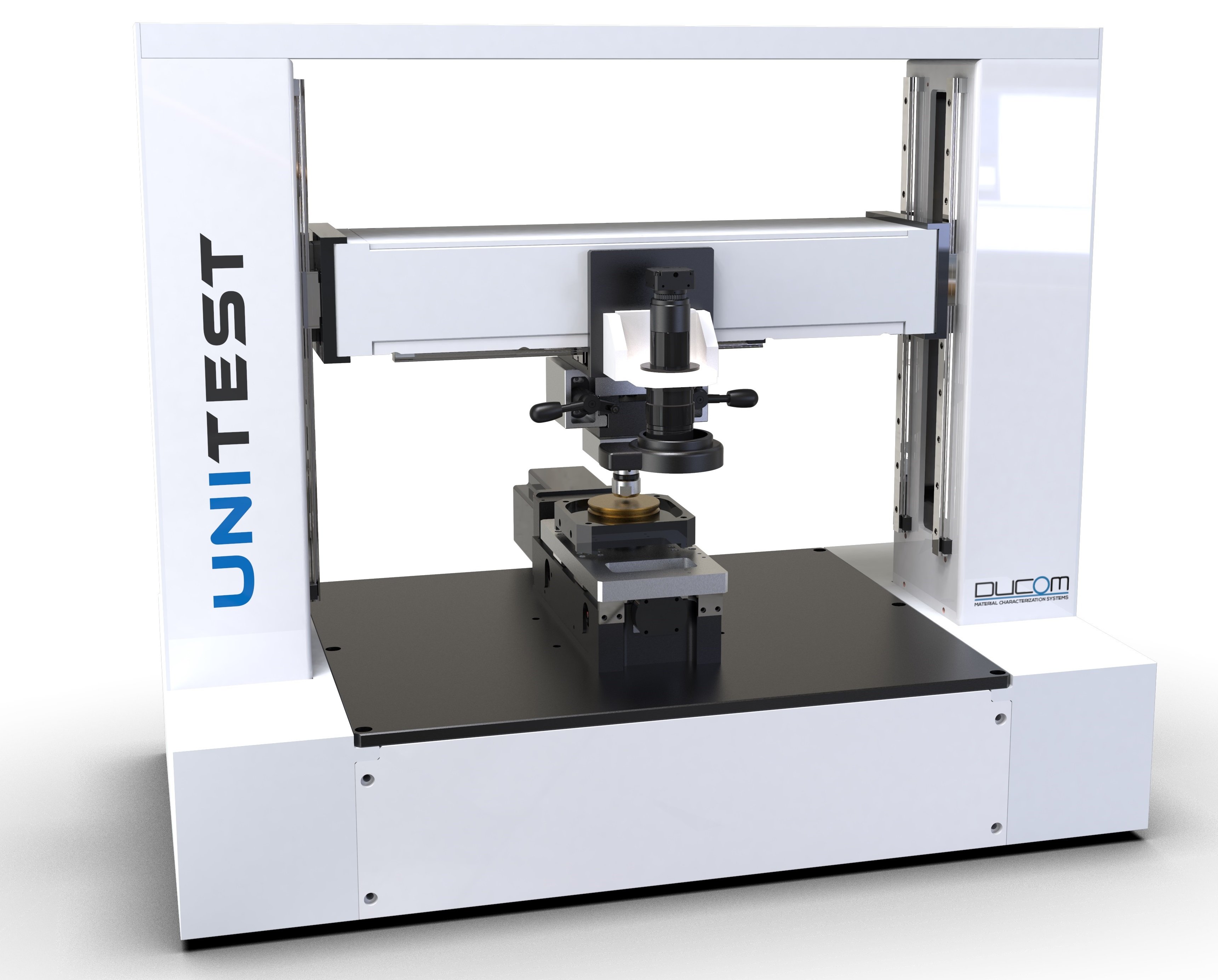
Figure 1. Unitest with a linear motion stage for scratch testing integrated with an optical imaging system. Advanced software can auto-stitch the scratch image and overlay on the force measurement graph.
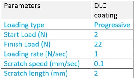
A standard Rockwell diamond indenter tip of radius 200 µm was used in scratching the DLC coating. The scratch test parameters are as given in Table 1. Accurate evaluation and repeatability is ensured with a Rockwell diamond tip having no defects (cracks, chips and pits). A good stylus for scratch testing was identified using a combination of optical microscopy and 3D optical profilometry modules. (Refer supplementary information)
Table 1. Scratch conditions for DLC coating on steel substrate (HRc 62)
Coating Failure Modes
Using inline imaging and characteristic friction force signatures corresponding to the coating failure modes, we have identified multiple failure mechanisms for DLC coating (see Figure 2)
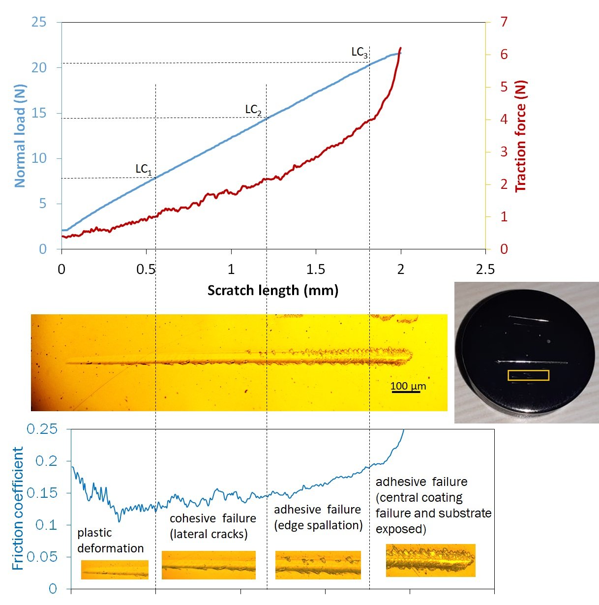
Figure 2 Real-time normal load, tangential force and stitched optical image from the Ducom Unitest. Correlation of progressive failure mechanisms with friction coefficient (measured between stylus and coating) is also highlighted.
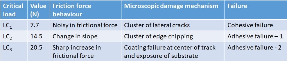
The critical failure loads are given in Table 2 that was based on visual observation and correlation with friction force response in Ducom Unitest. Three different damage mechanisms were identified, as described below.
Table 2 Description of critical failure loads and failure mechanisms for DLC coating.
Load < Lc1
In this region, the coating experiences plastic deformation with no visible damage. The traction (friction) coefficient value was between 0.1 and 0.15 which is reasonable for DLC coatings.
Lc1 < Load < Lc2 (Cohesive Failure)
In this region, relatively small lateral cracks form at the edge of the track as isolated events. Such through thickness cracks in the direction of scratching are caused by tensile stresses behind the stylus. Friction force signature due to cracking becomes noisy.
Lc2 < Load < Lc3 (Adhesive Failure - 1)
In this region, isolated edge chipping transitions into clusters with increasing load. Such cracks are caused either by cracking and lifting (buckling) or full separation (chipping) mostly due to compressive stresses. There is an associated change in the slope of the friction force as the stylus comes in contact with the damaged coating at the edges of the track.
Load > Lc3 (Adhesive Failure - 2)
In this region, delamination extends beyond the edge to the center of the track to separate the coating in patches and finally leads to gross spallation. The stylus advances on a rough track having contact with both the coating and the underlying substrate with a sharp increase in friction force.
Such damage mechanisms (through thickness cracking, chipping and spallation) are characteristic of thin brittle coatings on ductile substrates as highlighted in Table 3.
Table 3. Failure mechanisms in different coating-substrate combinations (adapted from Bull, 1997, Tribology Intl)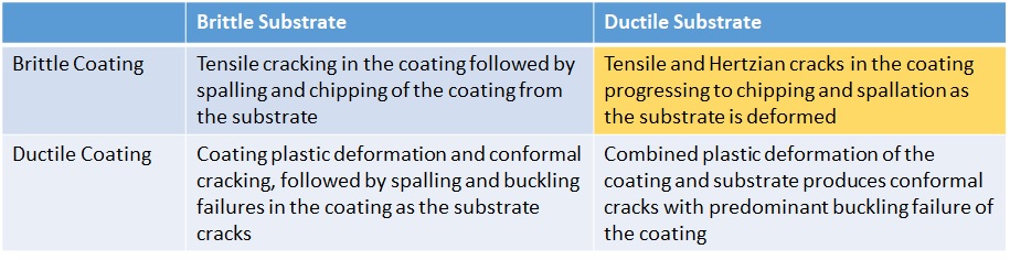
Ducom Unitest with Inline Imaging and high fidelity friction force sensor can identify and differentiate cohesive and adhesive failure modes during during scratch of advanced coatings. It offers a high performance platform for research and scientific insights on durability and damage tolerance of next generation surface engineering modifications.
Learn More About Ducom UniTest.
Supplementary Material (Diamond Stylus Imaging)
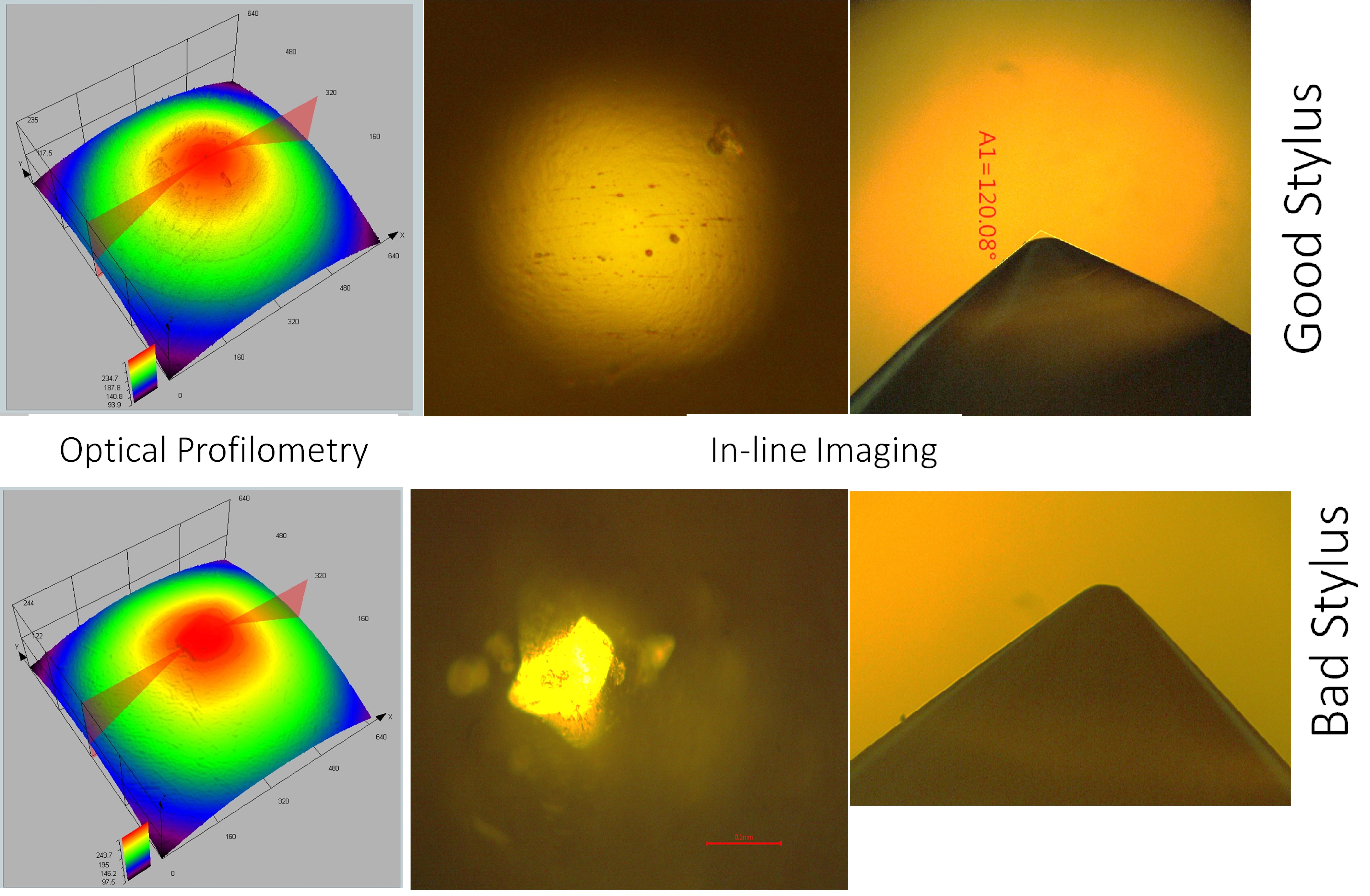
Figure 4 Optical profilometry and microscopy imaging to identify good and bad diamond styli. A symmetric contour profile (profilometer) and smooth reflective surface (microscopy) imply a good stylus which will provide accurate and repeatable results. The bad stylus has facets and a plateau at the tip rather than a hemispherical geometry. Ducom Unitest platforms offer both 3D non contact profilometry and optical imaging.
%20-%20PNG.png?width=925&height=246&name=Ducom%20-%20Logo%20-%20Full%20-%20Vector%20(90%20Gray%20and%20Light%20Blue-Inverted)%20-%20PNG.png "Ducom - Logo - Full - Vector (90 Gray and Light Blue-Inverted) - PNG")


.png?width=564&height=150&name=Ducom%20-%20Logo%20-%20Full%20-%20Vector%20(90%20Gray%20and%20Light%20Blue-Inverted).png "Ducom - Logo - Full - Vector (90 Gray and Light Blue-Inverted)")