Tribological investigation will be incomplete without high quality surface characterization which helps to investigate the wear damage mechanisms. Scratch testing using an ideal single asperity contact i.e., a diamond stylus, is widely used for identification of failure modes and critical load at failure ( or adhesion). Often several complimentary techniques are required to capture and correlate critical damage events with high confidence levels. Ducom Unitest Scratch Tester (see Figure 1) offers an open architecture platform featuring loading and motion modules integrated with high resolution inline imaging, acoustic emission and depth sensors.
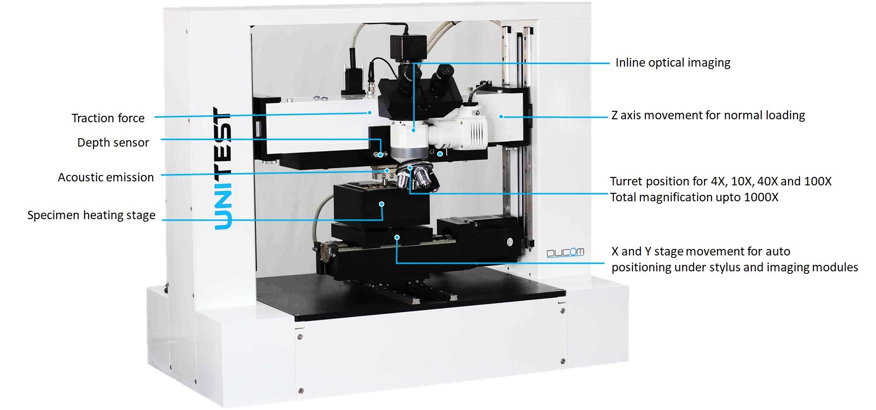
Figure 1. Unitest Scratch integrates loading, X-Y-Z motion module, temperature stage, imaging, traction force, depth and acoustic emission sensor on a single instrument
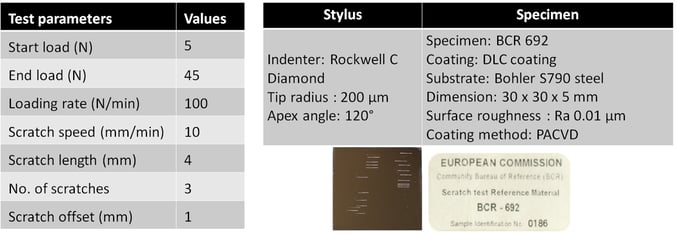
To establish the performance of Unitest Scratch Tester, a certified reference material, DLC coating (BCR 692), developed by the Institute of Reference Materials (IRMM) and Measurements, European Commission Joint Research Center, Belgium, was tested as per the conditions given in Table 1. Friction force, acoustic emission, temperature, humidity, velocity, load and wear were acquired in real time and surface images of scratches were processed in situ.
Table 1. Test conditions and stylus as per guidelines for BCR 692. Multiple scratches by Ducom Unitest on BCR 692 specimen.
A short video of Ducom Unitest in action, as it creates a single scratch on the sample, post-test imaging using in-line optical module, stitching and complete research report generation.
Unitest Scratch video showing scratch, imaging and analysis interface of stitched track superimposed with data from various sensors.
A representative plot of acoustic emission and traction force profiles generated during scratching that is mapped to the stitched image of the scratch on BCR 692 is shown in Figure 2.
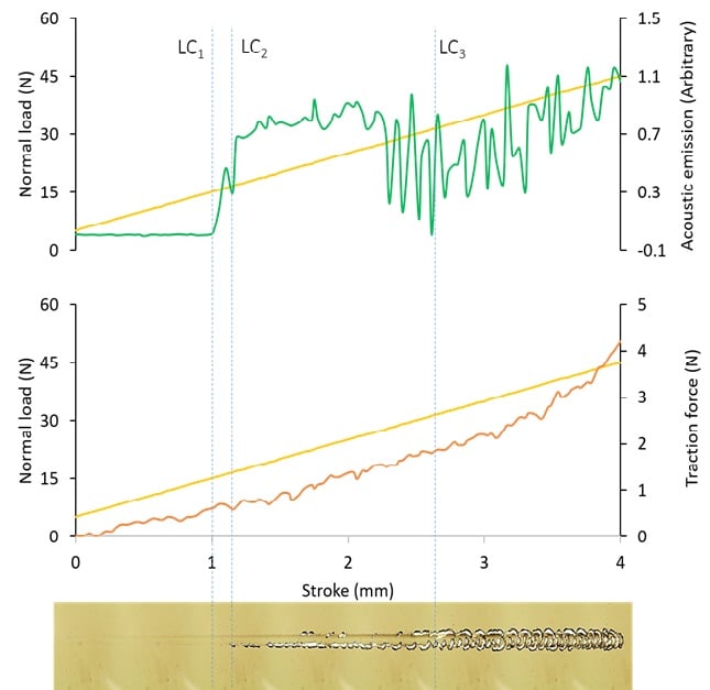 Figure 2. Acoustic emission and traction force profiles can be mapped onto the stitched scratch image to accurately identify damage and correlate signals from different sensors
Initiation of edge cracks marks the first critical wear for BCR 692 sample. However, such tight short length cohesive failures in the coating, are barely visible even in the best optical imaging systems. However, acoustic emission intensity mapped over the scratch length showed a steep rise at a length of ~ 1 mm from the start of the scratch, thereby unambiguously establishing formation of edge cracks. Further progressive damage with increasing loads lead to edge spallation and central cracking which could be simultaneously identified from the image, acoustic emission intensity as well as change in traction force (Figure 2). A magnification up to 1000X coupled with auto-positioning accuracy of 1 micron was used to capture high fidelity images of localized damage. Figure 3 illustrates the standard failure modes for BCR 692, this is in correlation with the failure modes demonstrated by Ducom Unitest for the same reference materials.
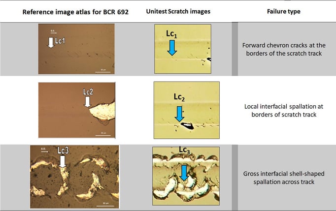
Figure 3. Standard failure modes for BCR 692.
The critical failure loads for the cohesive (Lc1) and multiple adhesive failures (Lc2 and Lc3) were determined by measurement of the location from the origin of the scratch and using equation 1
Lci = 10xi + 5 ----------(equation 1)
where Lci = critical failure load for a specific failure mode, xi = distance from scratch start to failure initiation point measured on the image, 10 N/mm = loading rate and 5 = initial load in N (as per Table 1.) Accurate measurements of xi are critical in determining failure loads and this was automated using digital tools embedded within WinDucom interface (Figure 4, top image). The mean failure load with standard deviation for three scratches on BCR is reported. (Figure 4, bottom image).
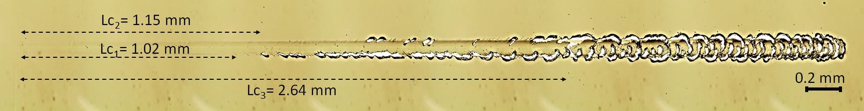
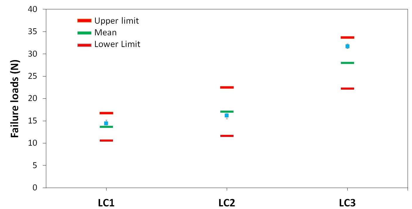
Figure 4. Shows the measured location for different failure modes using in-built calibration (top image). Precision limits for different failure loads obtained in Ducom Unitest (bottom image).
The reported failure loads for all three scratches on BCR 692 were within the precision limits reported by the standard thereby validating the scratch test by Ducom Unitest.
In summary, Ducom Unitest with scratch module is embedded with multiple sensors, and automation modules for high throughput scratch testing. It has demonstrated a controlled loading and motion profiles with high accuracy. Furthermore, high resolution inline imaging, traction and acoustic emission sensors are combined to deliver insights on the progressive damage and durability of coatings.
%20-%20PNG.png?width=925&height=246&name=Ducom%20-%20Logo%20-%20Full%20-%20Vector%20(90%20Gray%20and%20Light%20Blue-Inverted)%20-%20PNG.png "Ducom - Logo - Full - Vector (90 Gray and Light Blue-Inverted) - PNG")


.png?width=564&height=150&name=Ducom%20-%20Logo%20-%20Full%20-%20Vector%20(90%20Gray%20and%20Light%20Blue-Inverted).png "Ducom - Logo - Full - Vector (90 Gray and Light Blue-Inverted)")